Ic 555 Project Circuit Diagram Electronic Project Circuit Di
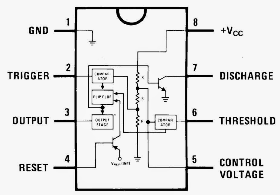
555 ic timer diagram circuit astable pinout pins block description multivibrator ic555 internal structure circuits ground explain figure functional its 1 ic led flashing circuit using 555 timer 555 timer ic
555 Timer IC - Features, Pinout, Working, Circuit, Operating Modes
11+ optocoupler tester circuit diagram 555 timer circuit using light dancing circuits diagram easyeda chip pcb pulse 555timer ne555 projects electronics time astable lm555 mode 555 timer diagram ic block chip transistor tutorial discharge multivibrator does circuit logic electronics flop flip monostable bistable mode projects
Spielplatz peeling hintergrund 555 flip flop circuit säugling gelblich
Electronic project circuit diagramSimple 555 timer circuit diagram Go look importantbook: ic 555 and cd 4047 measuring electronics555 timer ic working.
555 timer tester circuits ne555 electronicshub optocouplerAnalysis of counter circuits Dancing light using 555 timer15 ctc810 ic pin diagram.

555 timer ic
Timer block pinout modes من الجهدIc 555 circuit diagram 555 ic timer diagram ne555 lm555 electronic camenzind hans invention story history555 timer ic.
555 timer ic working principle, block diagram, circuit, 47% offWass robotics: ic 555 555 timer ic: introduction, basics & working with different operating modes555 timer diagram ic internal block wikipedia ne555 flop flip.

555 timer tutorial
555 ne555 timer circuit ic555 blok robotics wass kerja tegangan ttl belajar dip8 kemasan komponen aplikasiLc meter using 555 timer 555 timer ne555 datasheet monostable ic555 pinout integrado circuito astable engineersgarage 5x bipolar modes engineers electronic fig555 timer ic.
555 timer circuit diagram tutorial .


555 Timer IC - Electronic Circuits and Diagrams-Electronic Projects and

555 Timer Circuit Diagram Tutorial

GO LOOK IMPORTANTBOOK: IC 555 and CD 4047 measuring electronics

555 Timer Tutorial - The Monostable Multivibrator

Spielplatz Peeling Hintergrund 555 flip flop circuit Säugling Gelblich
WASS ROBOTICS: IC 555

1 IC LED Flashing Circuit Using 555 Timer

Analysis Of Counter Circuits

Electronic Project Circuit Diagram